.png)
Generic Truss-rod Flatcar
by Martin Brechbiel
All photos by author Adapted from Scale Rails Nov. 2004
Also check Flatcar to Gondola conversion.
Step 1 Construction begins with building a box which serves as the perimeter frame of the flat car. You need to find the two 6" x 12" x 8 ½’ end sills and the two 6" x 12" x 38’ side sills for building a box (Fig 1).
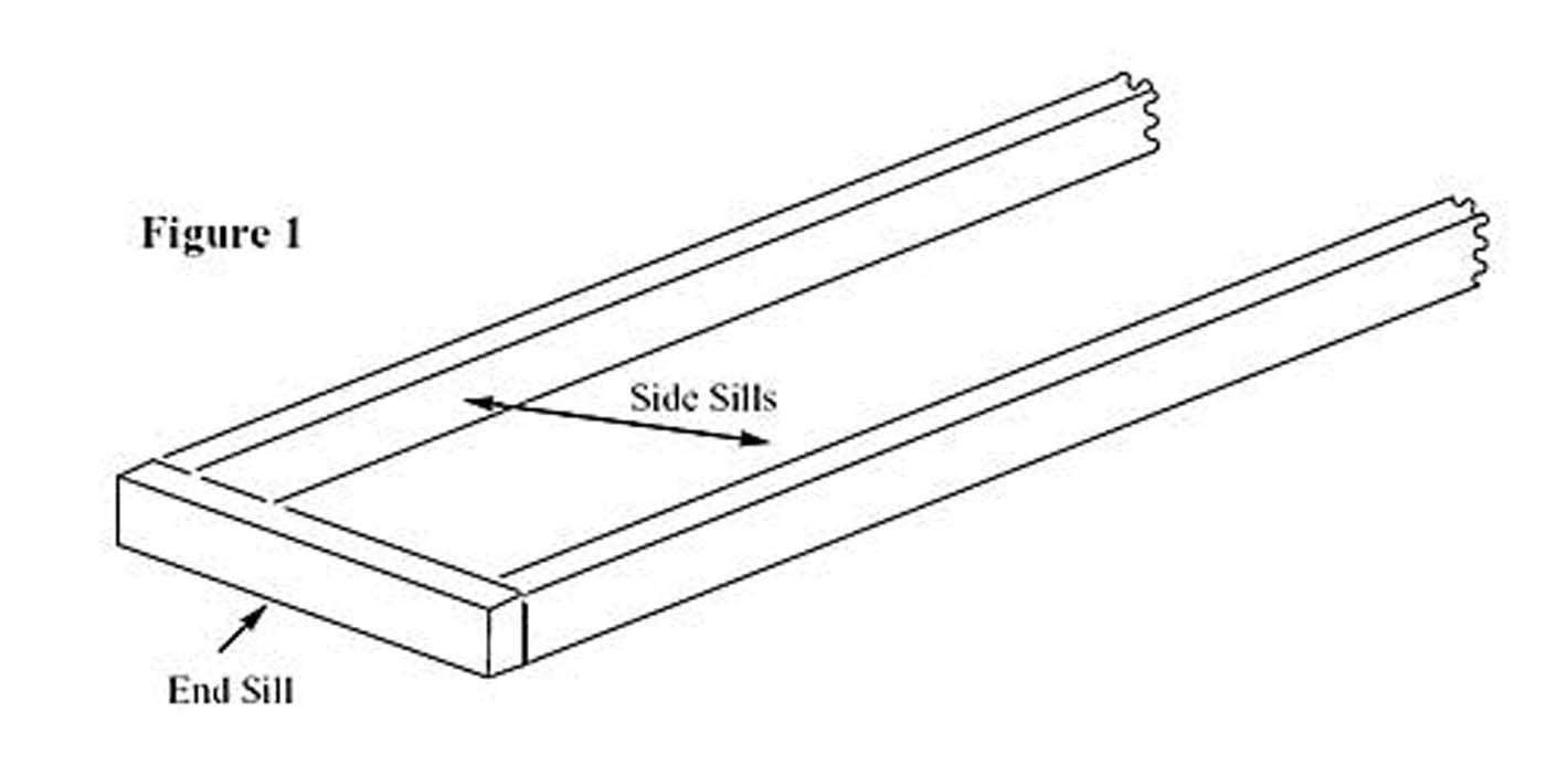
Make sure that these paired pieces are exactly the same in length, and if not, sand them to match! Also, at this time make sure that the interior beams also match the length of the side sills. And, one part of this is to not worry about the length being exactly 38'; your car can be shorter, longer, narrower, whatever you would like it to be. One of the fundamentals here is to take a pile of sticks and come up with a credible, generic truss-rod flatcar.
If you feel creative you could assemble these parts using simple or complicated lap joints, but that is not always practical so we'll make do with a butt joint. The use of Walther's Goo is recommended for this step since wood glues and ACC are notoriously weak for this kind of joint. A small dab on the ends of the side sills will serve to assemble the frame and allow you to adjust it at your leisure to get square. I trust my eyes, but you can verify square using a small machinist or carpenters square or by measuring the diagonals; these should be equal in length. This Goo step is to just set up the frame for the next step - putting on the decking. Don't worry about putting the other 4 beams in just yet; these go in much easier after the decking is in place!
Step 2 Scribed sheet is really too neat and tidy looking. And, unless you use two sheets back-to-back you don't get the visual effect of boards from the underside, for those that do look under their cars. We'll use individual boards and not those nice and smooth scale boards, but something that provides random widths and having a rough, worn surface that ages the appearance to add some surface character. We'll use wooden coffee stirrers. There's a commercial model building source of these, Doctor Ben's Rustic Lumber, but you can buy a case of 10,000 pretty cheaply. These tend to come in random widths (5-8") and a useable thickness (~2 ½") for this car in 'O' scale. One thing you have to carfe about is that these are not basswood; they are a hardwood, probably birch, so cutting these can be a little tricky. I use a band saw and a heavy utility knife as needed and sometimes use a 4" belt sander for finishing.
There ~80 deck boards supplied pre-stained to deck this car. These are cut close to, but a bit longer than the needed width. You can trim the excess later or if you are very careful, align these for an overhang. One caution about wood, you can trim it later, but it's hard to lengthen it if you've cut it too short early on. Now, pick out 4-6 "nice", straight deck boards and after laying down a bead of CA on the top of the end sill and about the distance of what would be ~3 deck boards down the side sills, glue down ~3 deck boards (Fig. 2).
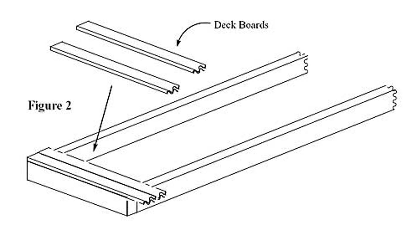
Do this at each end and be careful not to disturb your nice square frame! Press these boards down firmly and try to not glue yourself to the car. Repeat from the other end of the car frame. With these two operations completed your car frame is set and you can insert the interior stringers.
Step 3 Flip over this assembly and now you can drop in your four 4" x 12" x 38' stringers (Fig. 3). These can be spaced equidistant or not, but should be symmetric. Depending of the car and type of truck bolster, their placement can vary both in spacing and in size.
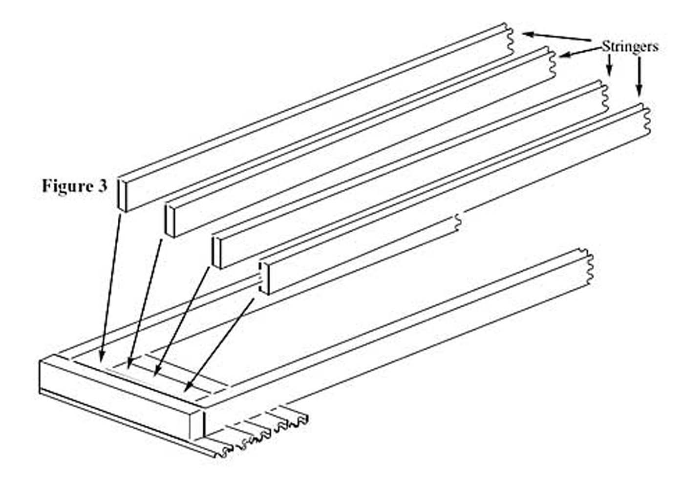
Make sure they fit with minimal friction; you don’t want to bow these into place. Sand and test fit until they fit, but again, don’t sand too enthusiastically, reversing the process does not work very well. A dab of Goo on the end and a bead of CA on the surface o the stringers towards the underside of the decking that you did at each end locks each stringer into place. Now flip your assembly back over, run beads of CA down the tops of the side sills and the interior stringers and glue down your deck boards.
Try to pick “interesting” boards, color, grain, "knots", but also stay with the straight ones and try to avoid any that are not unless you can match up complementary boards. As you get close to meeting the two ends of deck boards that you are laying from each end, start laying out those you want to use to finish the remaining open section in advance. You do not want to end up with an awkward gap, but rather with a space close in width to a board you have picked out that can be "massaged" or sanded into place. After this step is completed and the glue is set, you can trim the deck boards flush with the side sills or trim them to suit your personal design.
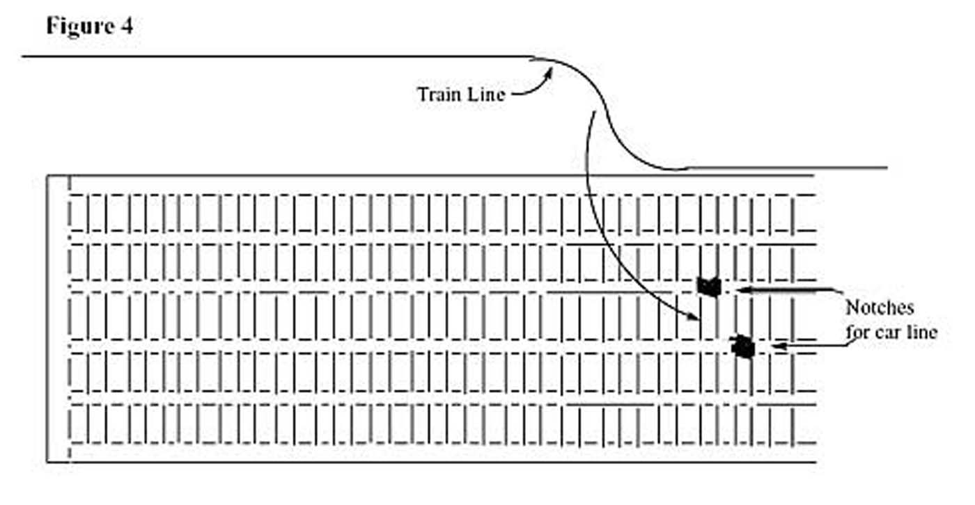
Step 4 Let's get into some of the underbody parts and details. Flip the assembly over again. If you want to put a train line in, now is the time. Form this from 0.28 wire with an "S" curve and place into some notches cut with a sharp knife into the center 2 stringers (Fig. 4). If desired, addition of a glad hand to the end this wire dresses up the end of the car nicely. A dab of Goo in those notches holds this wire in place.
To really anchor this, you need to put in the body bolsters where the trucks will be mounted. There are a host of commercial choices in brass, plastic, and even wood, and as you might guess, the choice here is wooden bolsters or copies that I've made cast in resin. However, if you manage to locate some old white metal or bronze castings the added weight is a great addition. The bolsters straddle the entire underbody resting on the side sills and all of the support beams in between. Secure these with some CA on all 6 contact points centered 6 ½" in from end of the car (Fig. 5).
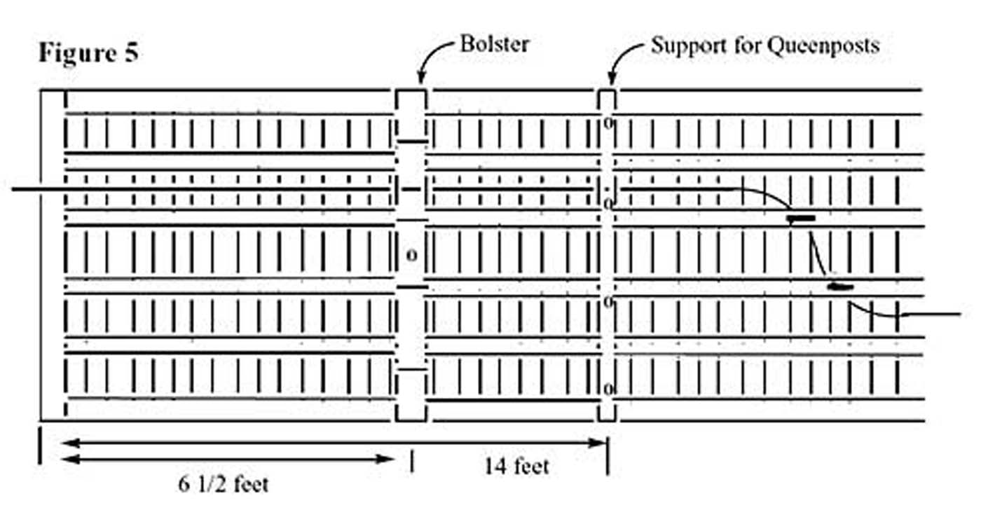
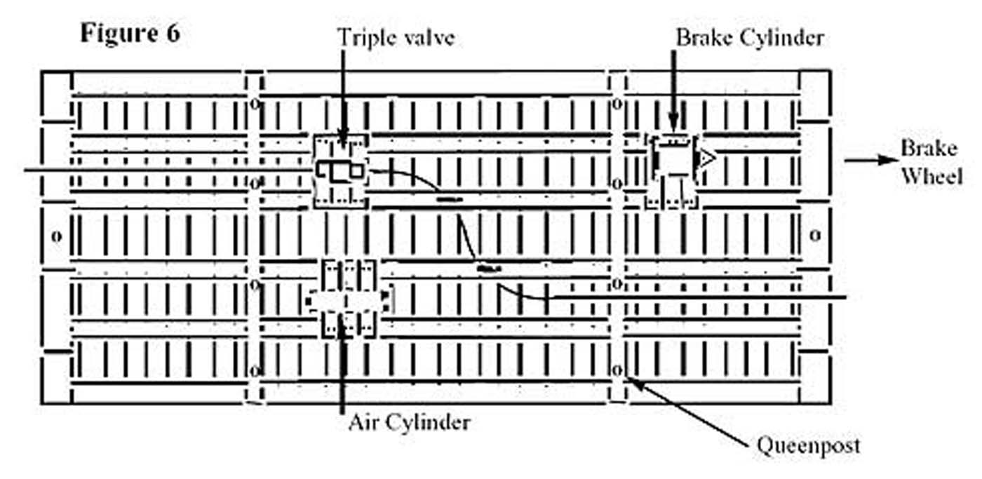
While on this side of the car you can address placement of the remaining structural part, some details, and the brake system. The 2 cross-members (6" x 6" x 8 ½') that the queen posts will be mounted on can be set into place. Glue these down with CA 14 feet in from the end of the car (Fig. 5). Brake options - this comes with an AB brake system supplied, but that can be exchanged for an earlier K brake casting. 6 Take some of your leftover decking boards and fashion mounting platforms for the brake components; triple valve, air cylinder, and brake cylinder (Fig. 6). Use 3-4 boards for each brake casting straddling 2 of the stringers and secure them with CA.
Think ahead at this point about where the truss rods and turnbuckles need to run through this maze you're creating so that you leave four pathways.
After the glue is dry, if you like, you can dress up these boards with some nut-bolt-washer (nbw) castings from Grandt Line.
Mount the brake system; the supplied parts, either AB or K brake components, are nice, heavy metal castings (Old Pullman, All Nation, others) so there's a little filing to clean these up, but the added weight contributing to a lowered center of gravity is a bonus for wooden cars in any scale.
While I drill these out for 0.022 brass wire to make plumbing for a brake system that can be tied to the train line, we'll forgo that exercise this time. These parts have rather large casting sprues that are used as mounting posts. Match these sprues up with a drill bit and drill a hole in the appropriate mounting platform you made previously, again keeping in mind that you need to leave a path for your truss rods. Be really careful drilling this hole so you do not tear up your platform or get too aggressive and hit your decking boards just a scale foot on the other side. A dab of Goo on the sprue and the base plate of each component and gently place these in their respective holes; you may have to also to nip the sprue if it's too long for the part to set on its base plate. You could nip the sprues off entirely and rely on the base for mounting, but you'll lose a lot of mounting strength.
Step 5 Since you've been thinking about where you are going to put those truss rods, let's get those installed now. Drill holes in the cross member to mount the queen posts (Fig. 6). The 5" queen posts are Grandt Line #68 and the "bolt" off the sprue can be accommodated by a #67 drill bit. Drill 4 holes with a pin vise (or a hand drill or drill press) in each cross member, carefully cut each queen post from the sprue at an angle using a sharp knife. A bit of CA on the bolt and application of gentle pressure with that angle cut and each queen post will drop right in. Make sure you have these aligned correctly so that the truss rod running from end to end will rest correctly on the queen post. Now that these are mounted, you can drill holes in the ends of the end sills for the nbw's that are to represent the ends of the truss rods. These are again from Grandt Line (#16 or #81) and there are several styles to chose from and usually require a #58 drill. I like to use the ones with a nice big round or square washer that shows nicely after painting. You can drill these holes with a pin vise again, or as I do, with a hand drill. You need 4 in each end to correspond with the 4 pairs of queen posts and these should be aligned in a straight line. But, before you put these in, let's address those pesky truss rods and the turnbuckles.
There are two (and probably a lot more…) options that can be used. Here's what we'll do - we'll use 0.022 or 0.018 brass wire for truss rods and either # 54 Grandt Line or a CMA "S" scale turnbuckles. Take a length of wire, Detail Assoc., and since these are ~ twice the car length, you can cut them in half. Thread one end under the car bolster and secure that end part way into one of the drilled holes with a dab of Goo in the end sill. Line the other end up onto the queen post and very(!) carefully bend the wire until the portion between the queen posts is parallel. Repeat this process for the remaining seven portions. Nip the overlapping ends very close as if attempting to connect them together. Look at a turnbuckle casting to see just how close the two ends have to be from each other and still be linked by the casting before cutting. Take a turnbuckle casting and thread it onto one end of a truss rod completely and then while pulling it ~½ off, thread it onto the corresponding other ½ of that truss rod. Secure everything with minimal CA and repeat for the remaining 3 truss rods. Now you can insert those large nbw's into those holes on the end sill.
Step 6 Now, you're almost finished. Just add the stirrup steps and the brake wheel with ratchet & pawl assembly. The #83 Grandt Line stirrup steps at each corner are applied by first drilling #72 holes that correspond with the bolts on these castings followed by glue with a drop of CA on each bolt with a discrete amount on the surface towards the car side sill (Fig. 7). The brake wheel casting assembly, Grandt Line #33, tends to be very delicate.
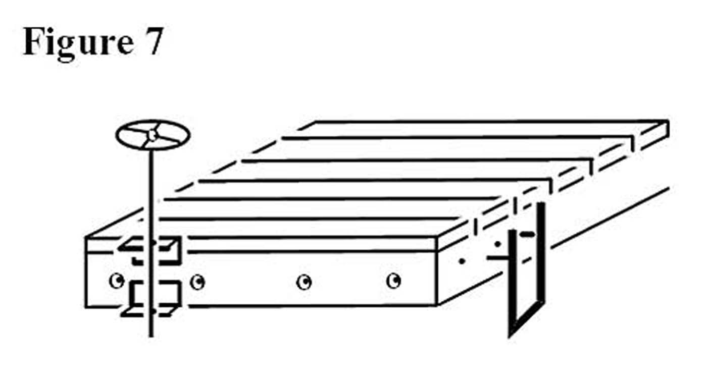
Carefully ream out the center of the brake wheel with a #72 drill and glue a short length of 0.022 brass wire so that the end is nearly flush with the top of the wheel. Similarly, ream out the hole in the gear. Very, very carefully, with a sharp knife, free the wheel from the casting sprue. Similarly free the gear and ratchet casting and thread this on the brake shaft and set this aside. I like to use 3/32 Plastruct or Evergreen styrene angle to mount the brake assembly. Cut 2 pieces roughly 6" long and drill a #72 hole centered and aligned in each (Fig. 7). Glue these to the end still (Goo is preferred) that the brake cylinder is pointed towards; one flush at the top of the decking boards and the other flush to the base of the end sill with the two holes aligned. Now, carefully pass the brake shaft through the two holes from above so the gear and ratchet rest partially on the angle and the decking. Secure all with either CA or Goo with the brake wheel at a reasonable height.
Final options include grab irons and stake pockets to dress up that otherwise naked car side. To add weight, build a load for your flat car! Arch bar trucks would be appropriate and the plastic Athern trucks are fine, but you can replace the wheel sets with metal wheels for smoother rolling and a lowered center of gravity weight. Mount these with a small wood screw. Finally, to add some Kadee couplers you'll have to add a block from the scrap box between the 2 center stringers to mount the coupler box. I like to use 3/8" #0 wood screws for this. Check for height and you'll either add a washer or sand the bolster. Some paint, stains, weathering, and lettering if desired and you'll have a pretty good truss rod flat car that gets you started in scratch building in wood!
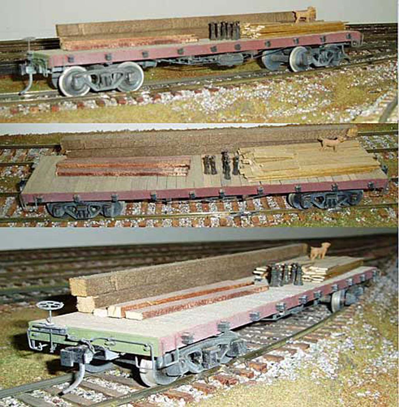
Here are some images of the finished flatcar
If you liked this tutorial you should check out the variety of tutorials located on the Potomac NMRA Clinics page.